Flow Dynamics and Pressure Instability at High Speed
Breakdown of Laminar Flow and Turbulence Onset Above 8,000 BPH
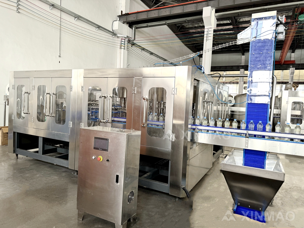
At low speeds, water moves through a bottled water filling machine in smooth, laminar sheets—predictable and uniform across nozzles. Above 8,000 bottles per hour (BPH), fluid velocity rises sharply, pushing the Reynolds number past its critical transition range. Flow shifts from laminar to turbulent: eddies form inside nozzles and downstream, creating non-uniform velocity profiles and cycle-to-cycle variation in effective discharge area. Some fill cycles deliver higher instantaneous flow; others, less—resulting in uneven liquid levels.
Sharp bends, small orifices, and rapid valve opening worsen this transition by inducing local acceleration and flow separation. Even minor geometric differences between nozzles become magnified under turbulence, causing the discharge coefficient to vary. Identical valve timing no longer guarantees identical volume. Operators commonly observe increased fill-level scatter only after crossing 8,000 BPH—a hard physical threshold, not a control limitation. Reducing speed below this point restores laminar behavior and tighter consistency. Sustainable high-speed upgrades must prioritize nozzle geometry optimization—not just faster valve actuation.
Cavitation and Air Entrainment Disrupting Consistent Volume Delivery
High flow velocity can drop local pressure below water’s vapor pressure, triggering cavitation. Vapor bubbles form in the nozzle throat and collapse violently downstream, generating shock waves and micro-jets that disturb the fill stream—and erode valve seats and sealing surfaces over time. As clearances grow, volumetric repeatability degrades.
Air entrainment compounds the issue. Air enters via seal leaks, vortexing in the supply tank, or splashing at high speed. Bubbles occupy volume without contributing mass. During filling, compressed air gives a false “full” reading to level sensors—leading to underfilled bottles. After bubbles rise post-filling, apparent levels drop, causing rejects.
Cavitation and air entrainment often co-occur, jointly undermining volume consistency. Mitigation includes increasing inlet pressure, smoothing flow paths, using larger nozzle throats, sealing all joints, maintaining adequate tank level, and installing vortex breakers. Without these measures, high-speed fill accuracy remains inherently unstable.
Manifold Pressure Variance Across Nozzle Banks Under Rapid Cycling
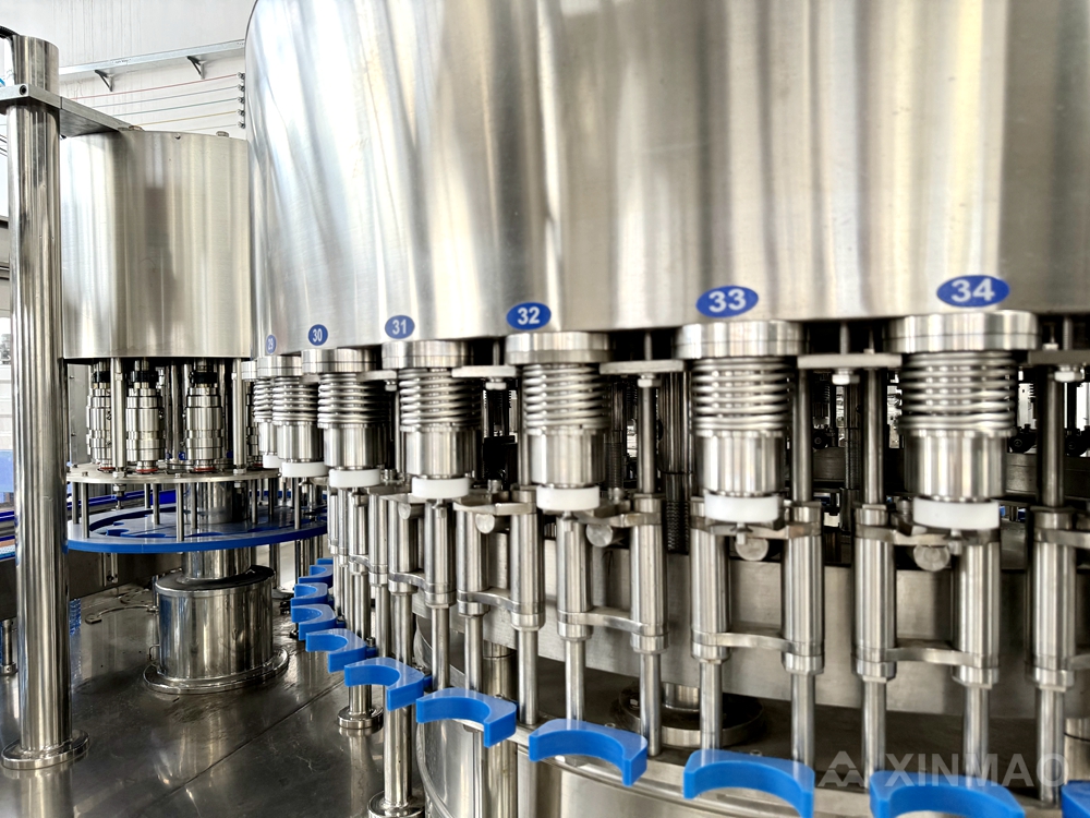
Rapid valve cycling generates pressure waves in the manifold. When one nozzle closes, water hammer sends a pulse through the system—felt asymmetrically by other nozzles due to propagation delay. Center nozzles typically experience stable pressure; end nozzles face larger fluctuations. A long, narrow manifold header amplifies this effect. At 10,000 BPH—where valve cycle times fall below 0.3 seconds—pressure recovery between cycles is incomplete. Measured pressure can swing by 0.1–0.2 bar across the bank, shifting fill volume by 1–2 mL per cycle. Over hundreds of bottles, the cumulative effect becomes visibly inconsistent.
Solutions include adding accumulators, increasing manifold diameter, tuning valve open/close ramps to reduce surge, or implementing individual nozzle pressure compensation. Without pressure balancing, outer nozzles consistently under-deliver—producing a repeatable fill-level drift pattern often misdiagnosed as calibration error. In reality, it reflects fundamental manifold hydraulics limitations.
Mechanical Wear and Alignment Drift in Critical Filling Components
Thermal Expansion-Induced Micro-Misalignment Across Multi-Nozzle Banks
High-speed bottling lines generate heat from servo drives, recirculating pumps, and product temperature shifts. Stainless steel nozzle banks expand ~17.3 µm per meter per °C. On a 2-meter manifold, a 15 °C temperature rise during startup induces ~0.5 mm of linear growth—rarely uniform, as cooler mounting brackets and frame rails constrain expansion. Differential movement shifts nozzle tips away from bottle centerlines. Even a 0.2 mm vertical or lateral offset disrupts the fill stream, causing short shots, foam, or overfill above 8,000 BPH.
Field audits show micro-misalignment typically emerges after 30–45 minutes of thermal stabilization and worsens with repeated hot-water sanitation cycles. Fluctuating fill heights often appear before any visible mechanical fault. Corrective actions include realigning nozzle banks after warm-up and verifying frame tie-rod torque.
O-Ring Compression Set and Seal Fatigue in Bottled Water Filling Machine Valves
Filling machine valves undergo thousands of open-close cycles per shift. Repeated compression causes permanent deformation—compression set—that reduces sealing force. Heat from sanitation, water treatment chemicals, and rapid pressure spikes accelerates fatigue, especially after hot sanitation cycles. Once elasticity is lost, product leaks past the seat, compromising fill consistency.
Maintenance data identifies seal and O-ring wear as the leading failure mode for beverage filling equipment, with fill accuracy drifting beyond ±1% before visible leakage occurs. Weekly seal inspections and quarterly valve overhauls help detect hardening, flat spots, and micro-cracks early. Using food-grade O-rings rated for operational temperature and chemical exposure extends service life. Without proactive replacement, uneven liquid levels persist—even after recalibration.
Calibration Decay and Control System Limitations
Servo-Piston Position Drift Beyond ±0.15 mL Tolerance Over Time
Fill accuracy degrades when servo-piston position error exceeds ±0.15 mL. Thermal expansion, seal drag, and encoder feedback degradation introduce small but compounding offsets over thousands of cycles. Though closed-loop control may hold the commanded target, the actual piston stroke drifts because the zero reference shifts. Operators often overlook this until weight checks flag underfills—or overfills increase giveaway.
Routine verification against a calibrated reference standard mitigates risk. High-speed lines benefit from shift-level position checks and automatic offset compensation. Left uncorrected, a 500 mL setpoint can settle at 500.17 mL or 499.82 mL—raising reject rates and eroding line efficiency.
Smart Monitoring Solutions for Real-Time Fill Level Correction
Capacitive Level Sensors vs. Timed-Fill Logic in Bottled Water Filling Machine Lines
Capacitive level sensors measure actual product height at each nozzle and trigger valve closure precisely at the target volume—correcting for real-time drift caused by pressure variance, turbulence, or mechanical shift. Timed-fill logic, by contrast, opens valves for a preset duration and assumes stable pressure and flow. As manifold variance increases above 8,000 BPH, timed-fill logic frequently underfills or overfills. Capacitive feedback closes the loop, preventing costly rework and reducing product giveaway.
FAQ
What causes flow dynamics changes above 8,000 BPH in bottled water filling lines?
Above 8,000 BPH, fluid velocity increases sharply, pushing the Reynolds number past its transition point from laminar to turbulent flow. Factors like sharp bends, small orifices, and rapid valve opening exacerbate the changes, resulting in uneven liquid levels.
How does cavitation impact fill consistency?
Cavitation occurs when local pressure drops below water’s vapor pressure, forming vapor bubbles that collapse violently downstream. This generates disturbances that reduce volumetric repeatability and leads to mechanical wear on valves and nozzles.
Why do nozzle banks misalign during high-speed filling operations?
Thermal expansion caused by heat sources like servo drives and pumps can induce differential movement across nozzle banks, shifting nozzle tips away from bottle centerlines. This misalignment disrupts the fill stream and adversely affects consistency.
How can pressure variance in the manifold impact fill levels?
Pressure waves caused by rapid valve cycling generate uneven manifold pressures across nozzle banks. This results in inconsistent fill volumes, especially for end nozzles, and requires solutions like accumulators or individual nozzle pressure compensation.
What solutions improve fill consistency at high speeds?
Key solutions include optimizing nozzle geometry, adding vortex breakers, performing regular maintenance on seals and valves, realigning nozzle banks after thermal stabilization, and using capacitive level sensors for real-time corrections.
Are timed-fill logic systems reliable for high-speed lines?
Timed-fill logic systems may struggle with inconsistencies caused by turbulence and manifold variance. Capacitive level sensors provide more reliable corrections by measuring actual product height and ensuring precise valve closure.
Table of Contents
- Flow Dynamics and Pressure Instability at High Speed
- Mechanical Wear and Alignment Drift in Critical Filling Components
- Calibration Decay and Control System Limitations
- Smart Monitoring Solutions for Real-Time Fill Level Correction
-
FAQ
- What causes flow dynamics changes above 8,000 BPH in bottled water filling lines?
- How does cavitation impact fill consistency?
- Why do nozzle banks misalign during high-speed filling operations?
- How can pressure variance in the manifold impact fill levels?
- What solutions improve fill consistency at high speeds?
- Are timed-fill logic systems reliable for high-speed lines?