Why a Bad Bottling Plant Layout Costs More Than the Equipment Inside It
A beverage factory that installed a 24,000 BPH filling line but routes bottles through a 90-degree corner between the rinser and the filler, adds a 15-meter conveyor loop because the labeler was positioned on the wrong side of the packaging area, and stages finished pallets in the same aisle that raw materials travel through has spent $800,000 on equipment that will never run above 70% of its rated speed. The bottleneck is not the machine. The bottleneck is the bottling plant layout — the spatial arrangement of equipment, material flow paths, utility connections, and operator workstations that determines whether a production line runs at 100% capacity or limps along at two-thirds speed while operators wait for bottles to arrive at their station.
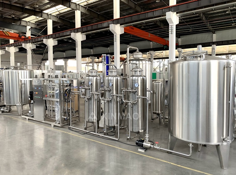
A correctly designed bottling plant layout follows one rule above all others: materials flow in one direction, never crossing back over their own path. Raw materials enter at one end of the facility — empty bottles from the bottle blowing machine or depalletizer, treated water from the water treatment system, syrup and CO₂ from the blending room — and finished, labeled, packaged product exits at the opposite end without ever reversing direction, crossing an active forklift lane, or waiting in a buffer zone that the layout designer forgot to dimension. Zhangjiagang Xinmao Drink Machinery (Xinmao Machinery), with 20+ years of beverage engineering experience and 500+ running production lines across 80+ countries, designs turnkey bottling plant layouts that apply this unidirectional-flow principle to every line configuration — from 1,000 BPH semi-automatic water filling to 36,000 BPH fully automatic carbonated drink lines with isobaric filling.
The Five Zones of a Bottling Plant Layout
Zone Sequencing That Prevents Bottlenecks
A well-designed bottling plant layout separates the production floor into five sequential zones. Zone 1 — Raw Material Intake: water treatment output, syrup blending tanks, CO₂ storage (for carbonated lines), and empty bottle/container supply. Zone 2 — Filling Core: the rinsing-filling-capping monoblock machine, such as Xinmao's DCGF-series 3-in-1 unit that combines bottle rinsing, isobaric filling with 99% accuracy, and capping into a single compact footprint, minimizing the conveyor distance between these three critical operations. Zone 3 — Post-Fill Processing: labeling, coding, inspection, and any thermal processing (pasteurization for beer, hot-fill cooling for juice). Zone 4 — Packaging: shrink wrapping, carton packing, palletizing. Zone 5 — Finished Goods: pallet staging, warehouse transfer. Zone 1 touches Zone 2, Zone 2 touches Zone 3, and so on — no zone connects to a non-adjacent zone, so forklifts never cross production flow and operators never walk against the direction of bottle movement.
Real-World Application: An African Bottler's Layout Redesign
A bottled water producer in Mozambique had purchased a Xinmao Machinery 5-gallon production line but installed it in an existing warehouse with a U-shaped layout — bottles entered at the north wall, traveled south through filling, then looped back north for labeling and packaging, crossing the empty-bottle supply path at a 90-degree intersection. Production ran at 60% of rated speed because filled bottles at the labeling station had to wait for gaps in the incoming empty-bottle queue to clear the intersection.
Xinmao's engineering team redesigned the bottling plant layout as a straight-line configuration, relocating the packaging zone to the south wall so bottles flowed north to south without intersecting. Conveyor length was actually reduced by 12 meters (the U-loop was longer than the straight line), and line speed immediately reached 95% of rated capacity. The Mozambique producer recovered the layout-modification cost — approximately $18,000 for conveyor relocation and utility reconnection — within four months from increased output alone.
Frequently Asked Questions
What is the ideal conveyor distance between filling and labeling?
The minimum conveyor distance between the filler discharge and the labeler infeed should accommodate the accumulated bottles required for the labeler's continuous operation — typically 2–3 meters of accumulation conveyor per 10,000 BPH of line speed. This buffer absorbs the minor speed variations between the filler (which runs at constant speed) and the labeler (which may pause briefly for roll changes). Insufficient buffer distance causes the filler to stop every time the labeler pauses.
Should the water treatment system be located inside or outside the production hall?
Water treatment equipment (sand filters, carbon filters, RO membranes, UV sterilizers) is typically located in a separate room adjacent to the production hall — accessible for maintenance without entering the production clean zone, and isolated from the humidity and chemical exposure of the filling area. Xinmao Machinery's turnkey solutions include water treatment system integration with proper room separation in the bottling plant layout.
How much floor space does a 24,000 BPH carbonated drink line need?
A complete 24,000 BPH carbonated soft drink line — including bottle blowing, water treatment, syrup blending, rinser-filler-capper monoblock, labeler, packer, and palletizer — requires approximately 800–1,200 m² of production floor space depending on the packaging format (PET, glass, or can) and the level of automation in the packaging section. Xinmao provides floor-plan drawings with every turnkey line proposal.
What ceiling height is required for a beverage production line?
The filling monoblock machine (Xinmao DCGF-series) with its overhead syrup tank and CO₂ manifold requires 3.5–4.5 meters of clear ceiling height. Bottle blowing machines with integrated preform hoppers require 4.0–5.0 meters. Warehousing and pallet-staging areas require 6.0–8.0 meters for racking.
How do I plan utility connections in a bottling plant layout?
Electrical (3-phase 380V/220V, main cables routed in overhead cable trays), compressed air (8 bar, ring main around the production zone with drop points at each machine), CO₂ (for carbonated lines, piped from outdoor bulk tank to the filler manifold), water (treated water loop from the treatment room to the filler, CIP return line back), and steam (for pasteurization, if applicable). Xinmao's installation team marks all utility connection points on the layout drawing before equipment delivery.
Can an existing warehouse be converted to a bottling plant?
Yes — if the floor is level (maximum 3 mm deviation per 2 meters), the ceiling height meets equipment clearance, the drainage system is adequate (floor drains every 6–8 meters, sloped 1–2% toward the drain), and the electrical supply matches the line's total connected load. Xinmao Machinery has completed warehouse-to-bottling-plant conversions in multiple countries, including a recent 5-gallon line installation in Mozambique.